| MATLAB Function Reference | Search Help Desk |
| patch | Examples |
patch(X,Y,C)
patch(X,Y,Z,C)
patch(...'PropertyName',PropertyValue...)
patch('PropertyName',PropertyValue...) PN/PV pairs only
handle = patch(...)
patch is the low-level graphics function for creating Patch graphics objects. A Patch object is one or more polygons defined by the coordinates of its vertices. You can specify the coloring and lighting of the Patch. See the "3-D Modeling" chapter in Using MATLAB Graphics for more information on Patches.
patch(X,Y,C)
adds the filled two-dimensional Patch to the current Axes. The elements of X and Y specify the vertices of a polygon. If X and Y are matrices, MATLAB draws one polygon per column. C determines the color of the Patch. It can be a single ColorSpec, one color per face, or one color per vertex (see "Remarks"). If C is a 1-by-3 vector, it is assumed to be an RGB triplet, specifying a color directly.
patch(X,Y,Z,C)
creates a Patch in three-dimensional coordinates.
patch(...'PropertyName',PropertyValue...)
follows the X, Y, (Z), and C arguments with property name/property value pairs to specify additional Patch properties.
patch('PropertyName',PropertyValue,...)
specifies all properties using property name/property value pairs. This form enables you to omit the color specification because MATLAB uses the default face color and edge color, unless you explicitly assign a value to the FaceColor and EdgeColor properties. This form also allows you to specify the Patch using the Faces and Vertices properties instead of x-, y-, and z-coordinates. See the "Examples" section for more information.
handle = patch(...)
returns the handle of the Patch object it creates.
Unlike high-level area creation functions, such as fill or area, patch does not check the settings of the Figure and Axes NextPlot properties. It simply adds the Patch object to the current Axes.
If the coordinate data does not define closed polygons, patch closes the polygons. The data can define concave or intersecting polygons. However, if the edges of an individual Patch face intersect themselves, the resulting face may or may not be completely filled. In the case, it is better to break up the face into smaller polygons.
You can specify properties as property name/property value pairs, structure arrays, and cell arrays (see the set and get reference pages for examples of how to specify these data types).
There are two Patch properties that specify color:
CData - use when specifying x-, y-, and z-coordinates (XData, YData, ZData).
FaceVertexCData - use when specifying vertices and connection matrix (Vertices and Faces).
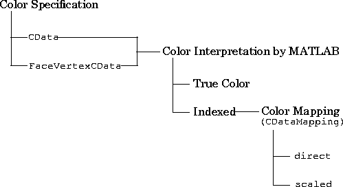
CData and FaceVertexCData properties accept color data as indexed or true color (RGB) values. See the CData and FaceVertexCData property descriptions for information on how to specify color.
Indexed color data can represent either direct indices into the colormap or scaled values that map the data linearly to the entire colormap (see the caxis function for more information on this scaling). The CDataMapping property determines how MATLAB interprets indexed color data:
CData and FaceVertexCData properties.
Interpretation of the CData PropertyXData, YData, ZData, and CData properties).
Vertices, Faces, FaceVertexCData, and FaceColor properties).
Specifying X, Y, and Z Coordinates
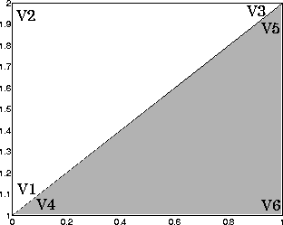
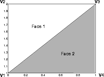
The first approach specifies the coordinates of each vertex. In this example, the coordinate data defines two triangular faces, each having three vertices. Using true color, the top face is set to white and the bottom face to gray:x = [0 0;0 1;1 1]; y = [1 1;2 2;2 1]; z = [1 1;1 1;1 1]; tcolor(1,1,1:3) = [1 1 1]; tcolor(1,2,1:3) = [.7 .7 .7]; patch(x,y,z,tcolor)
 Notice that each face shares two vertices with the other face (V1-V4 and V3-V5).
The
 Vertices property contains the coordinates of each unique vertex defining the Patch. The Faces property specifies how to connect these vertices to form each face of the Patch. For this example, two vertices share the same location so you need to specify only four of the six vertices. Each row contains the x, y, and z-coordinates of each vertex:
vert = [0 1 1;0 2 1;1 2 1;1 1 1];There are only two faces, defined by connecting the vertices in the order indicated:
fac = [1 2 3;1 3 4];To specify the face colors, define a 2-by-3 matrix containing two RGB color definitions:
tcolor = [1 1 1;.7 .7 .7];With two faces and two colors, MATLAB can color each face with flat shading. This means you must set the
FaceColor property to flat, since the faces/vertices technique is available only as a low-level function call (i.e., only by specifying property name/property value pairs).
Create the Patch by specifying the Faces, Vertices, and FaceVertexCData properties as well as the FaceColor property :
patch('faces',fac,'vertices',vert,'FaceVertexCData',tcolor,...
      'FaceColor','flat')
 Specifying only unique vertices and their connection matrix can reduce the size of the data for Patches having many faces. See the descriptions of the
 Faces, Vertices, and FaceVertexCData properties for information on how to define them.
MATLAB does not require each face to have the same number of vertices. In cases where they do not, pad the Faces matrix with NaNs. To define a Patch with faces that do not close, add one or more NaN to the row in the Vertices matrix that defines the vertex you do not want connected.
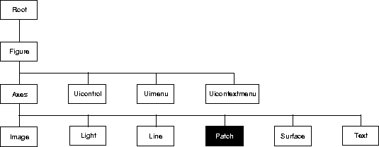
 You can set default Patch properties on the Axes, Figure, and Root levels:
set(0,'DefaultPatchPropertyName',PropertyValue...)
set(gcf,'DefaultPatchPropertyName',PropertyValue...)
set(gca,'DefaultPatchPropertyName',PropertyValue...)
Where PropertyName is the name of the Patch property and
PropertyValue is the value you are specifying. Use set and get to access Patch properties.
The following table lists all Patch properties and provides a brief description of each. The property name links take you to an expanded description of the properties.| Property Name |
Property Description |
Property Value |
| Data Defining the Object | ||
Faces |
Connection matrix for Vertices |
Values: m-by-n matrix Default: [1,2,3] |
Vertices |
Matrix of x-, y-, and z-coordinates of the vertices (used with Faces) |
Values: matrix Default: [0,1;1,1;0,0] |
XData |
The x-coordinates of the vertices of the Patch |
Values: vector or matrix Default: [0;1;0] |
YData |
The y-coordinates of the vertices of the Patch |
Values: vector or matrix Default: [1;1;0] |
| ZData |
The z-coordinates of the vertices of the Patch |
Values: vector or matrix Default: [] empty matrix |
| Specifying Color | ||
| CData |
Color data for use with the XData/YData/ZData method |
Values: scalar, vector, or matrix Default: [] empty matrix |
| CDataMapping |
Controls mapping of CData to colormap |
Values: scaled, directDefault: scaled |
| EdgeColor |
Color of face edges |
Values: ColorSpec, none, flat, interpDefault: ColorSpec |
| FaceColor |
Color of face |
Values: ColorSpec, none, flat, interpDefault: ColorSpec |
| FaceVertexCData |
Color data for use with Faces/Vertices method |
Values: matrix Default: [] empty matrix |
MarkerEdgeColor |
Color of marker or the edge color for filled markers |
Values: ColorSpec, none, autoDefault: auto |
MarkerFaceColor |
Fill color for markers that are closed shapes |
Values: ColorSpec, none, autoDefault: none |
| Controlling the Effects of Lights | ||
AmbientStrength |
Intensity of the ambient light |
Values: scalar >=0 and <=1Default: 0.3 |
BackFaceLighting |
Controls lighting of faces pointing away from camera |
Values: unlit, lit, reverselitDefault: reverselit |
DiffuseStrength |
Intensity of diffuse light |
Values: scalar >=0 and <=1Default: 0.6 |
EdgeLighting |
Method used to light edges |
Values: none, flat, gouraud, phongDefault: none |
FaceLighting |
Method used to light edges |
Values: none, flat, gouraud, phongDefault: none |
| NormalMode |
MATLAB-generated or user-specified normal vectors |
Values: auto, manualDefault: auto |
SpecularColorReflectance |
Composit color of specularly reflected light |
Values: scalar 0 to 1Default: 1 |
SpecularExponent |
Harshness of specular reflection |
Values: scalar >= 1Default: 10 |
SpecularStrength |
Intensity of specular light |
Values: scalar >=0 and <=1Default: 0.9 |
| VertexNormals |
Vertex normal vectors |
Values: matrix |
| Defining Edges and Markers | ||
LineStyle |
Select from five line styles. |
Values: -, --, :, -., noneDefault: - |
LineWidth |
The width of the edge in points |
Values: scalar Default: 0.5 points |
Marker |
Marker symbol to plot at data points |
Values: see Marker propertyDefault: none |
MarkerSize |
Size of marker in points |
Values: size in points Default: 6 |
| Controlling the Appearance | ||
| Clipping |
Clipping to Axes rectangle |
Values: on, offDefault: on |
| EraseMode |
Method of drawing and erasing the Patch (useful for animation) |
Values: normal, none, xor, backgroundDefault: normal |
SelectionHighlight |
Highlight Patch when selected (Selected property set to on) |
Values: on, off Default: on |
Visible |
Make the Patch visible or invisible |
Values: on, off Default: on |
| Controlling Access to Objects | ||
HandleVisibility |
Determines if and when the the Patch's handle is visible to other functions |
Values: on, callback, offDefault: on |
HitTest |
Determines if the Patch can become the current object (see the Figure CurrentObject property) |
Values: on, off Default: on |
| Controlling Callback Routine Execution | ||
|
Specify how to handle callback routine interruption |
Values: cancel, queue Default: queue |
|
Define a callback routine that executes when a mouse button is pressed on over the Patch |
Values: string Default: '' (empty string) |
|
Define a callback routine that executes when an Patch is created |
Values: string Default: '' (empty string) |
|
Define a callback routine that executes when the Patch is deleted (via close or delete) |
Values: string Default: '' (empty string) |
|
Determine if callback routine can be interrupted |
Values: on, off Default: on (can be interrupted) |
|
Associate a context menu with the Patch |
Values: handle of a Uicontrextmenu |
| General Information About the Patch | ||
Children |
Patch objects have no children |
Values: [] (empty matrix) |
Parent |
The parent of a Patch object is always an Axes object |
Value: Axes handle |
Selected |
Indicate whether the Patch is in a "selected" state. |
Values: on, off Default: on |
Tag |
User-specified label |
Value: any string Default: '' (empty string) |
Type |
The type of graphics object (read only) |
Value: the string 'patch' |
|
User-specified data |
Values: any matrix Default: [] (empty matrix) |