| Late-Breaking News for the MATLAB 5.2 Product Family | Search Help Desk |
Product Requirements
Stateflow is a multiplatform product, running on Microsoft Windows 95, Windows NT, and UNIX systems. Stateflow version 1.0.6 requires:http://www.mathworks.com/support/tech-notes/#mexSee the MATLAB Application Program Interface Guide for information on how to ensure proper installation for integration into the MATLAB environment. In addition, you can optionally use the Real-Time Workshop to generate floating-point code for Simulink portions of the model.
Enhancements
Version 1.0.6 fixes these bugs that were in Version 1.0:a = 1.0/2.0 translated to a = ½ in the generated code. The compiler, using integer arithmetic, set a equal to 0 instead of the intended 0.5.
min and max values that were not -Inf and Inf, respectively, resulted in generated code that did not compile.
sfc.m file.
Enhancements to the Sensor Failure Detection Demo
The Sensor Failure Detection demo in Stateflow 1.0.6 includes these enhancements:fuelsys model uses a new organization of the model objects, clarifying the interaction between the control logic and the engine model.
air/fuel mixture ratio. The air/fuel mixture ratio is monitored and displayed during simulation.
Overspeed state in the control logic.
Current Restrictions
A C or C++ compiler is required for creating MATLAB MEX-files on your platform. For an up-to-date list of compilers supported by MATLAB, see The MathWorks Technical Support Department's Technical Notes at:http://www.mathworks.com/support/tech-notes/#mex
Simulink Libraries and Stateflow Blocks
Stateflow blocks do not currently support Simulink libraries. There is a Machine properties dialog box for each machine. Currently this dialog box is accessible only through the Chart properties dialog box. The machine is shown in the Chart properties dialog box as the chart's parent. Clicking on the Parent field hypertext link displays the Machine properties dialog box. You can specify these fields in the Machine properties dialog box:Stateflow Finder and Case-Sensitive Searches
The Stateflow Finder performs case-sensitive searches based on the string criteria you enter. Currently you cannot specify a case-insensitive search. Spaces in the state name portion of a state label are not currently supported. For example, if you enteredstate one as one state's name and state two as another state's name (at the same level in the hierarchy), the parser would generate an error indicating the names are not unique.
Stateflow does not currently support an undo operation. However, delete operations copy the deleted objects to the paste buffer. You can undo a delete operation by immediately pasting the deleted objects.
Directed Event Broadcast Using send
As described in the Stateflow User's Guide, you can specify a directed event broadcast in the action language. The format of the directed broadcast is:send(event_name,state_name)
event_name is broadcast to state_name and any offspring of that state in the hierarchy.
Currently, you cannot direct the event_name to a state_name in another machine.
Sharing Workspace Data in a Real-Time Workshop Target
Sharing workspace data between two or more Stateflow charts in a Real-Time Workshop (RTW)target can cause a collision when these conditions are present:Real-Time Workshop RealTimeMalloc Code Format Option
The Stateflow Coder does not support the Real-Time WorkshopRealTimeMalloc code format option.
Graphics Editor Edit Menu and Text Labels
The Cut, Copy, and Paste menu items on the graphics editor Edit menu operate on Stateflow objects (states, transitions, and junctions). Text, such as a state or transition label, is not considered an object. Currently, when you edit a text label, the Edit menu is disabled during the edit operation.Known Software Problems
Resizing the Graphics Editor Window
If you resize the graphics editor window by quickly dragging the lower right-hand corner, the window may snap back to its original size. This behavior occurs only on PC platforms when opaque sizing is enabled.Stateflow Finder Dialog Box Cannot Be Resized
You cannot resize the Finder dialog box in this release.Stateflow Quick Reference Guide
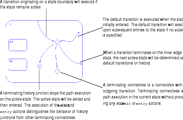
Graphics Editor
Action Language
S1.A to state S2.S3.C when event E occurs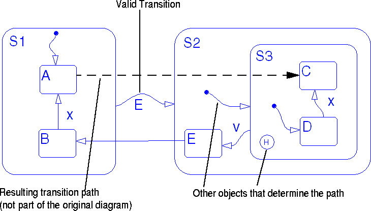
Searching for a Transition Path
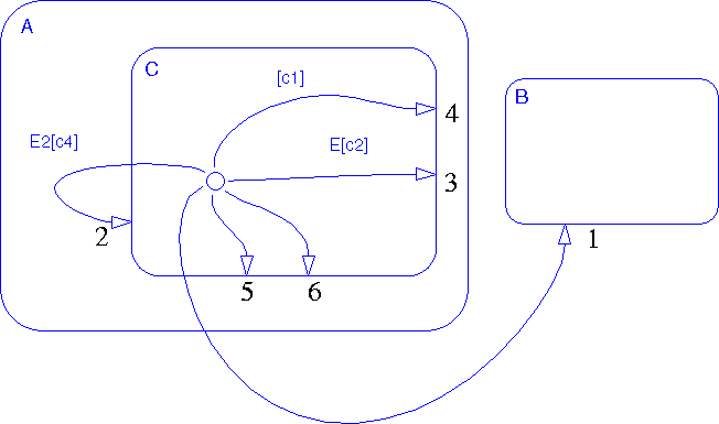
Stateflow uses a combination of hierarchy and ordering rules to determine the valid transition path. It is important to note that valid actions are executed during the path search. The path search begins with the active state; all transitions that originate from the active state are tested. Ordering rules determine the sequence in which the transitions are tested. If a transition branches or loops through a connective, the outgoing transitions from the connective are tested. Searching is terminated when the first valid path is found.during action.
on event_name action.
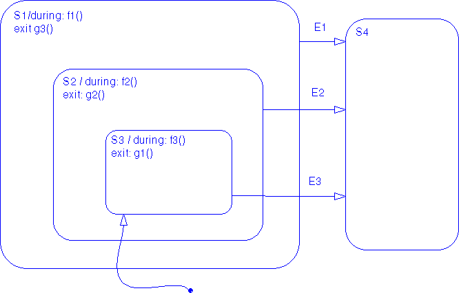 After the default transition executes, state
 S3 becomes active. The path out of state S3 is dependent on which event is broadcast:| Event Broadcast |
Result |
E1 |
No during actions are executed.
|
E2 |
The during action f1() is executed. |
E3 |
The during actions f2() and f3() are executed. |
exit actions will be executed in the order: g1(), g2(), and g3().
| Rule Priority |
Description |
Transitionfrom chart on page 5-15 |
| 1 |
Parent Rule: Transitions are sorted by the level of their parent. This means that outermost transitions are tested first. |
1, 2 |
| 2 |
Transition Label Rule: Transitions with the same level of parent are sorted by their label. The labels are considered in the following order:
|
3, 4, 5, 6 |
| 3 |
Transition Origin Rule: Transitions with the same level parent and the same type of label are sorted by their origin point using object geometry. The rule applies to both state and connective origins: |
5, 6 |
entry actions, state exit actions, and transition actions are executed as follows:
exit actions are executed just before a state is marked inactive.
entry actions are executed just before a state is marked active.
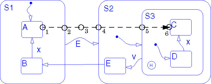
S1.A to S2.S3.C:
exit action of state S1.A executes and S1.A is marked inactive.
exit action of state S1 executes and S1 is marked inactive.
S2 is marked active and its entry action is executed.
S2.S3 is marked active and its entry action is executed.
S2.S3.C is marked active and its entry action is executed.
Frequently Asked Questions
This table contains frequently asked questions and their answers:| Questions | Answers |
| What are the differences among the terms Stateflow diagram, chart, and Stateflow block? | Using Stateflow, you create Stateflow diagrams. A Stateflow diagram is also a graphical representation of a finite state machine where states and transitions form the basic building blocks of the system. The term chart is used interchangeably with the term Stateflow diagram and is used as a shorthand representation in the GUIs. The Stateflow block is a masked Simulink model and is equivalent to an empty, untitled Stateflow diagram. Use the Stateflow block to include a Stateflow diagram in a Simulink model. The term Stateflow diagram is used from the Stateflow point of view, whereas the term Stateflow block is used from the Simulink point of view. |
| How do I load a Stateflow diagram? | Stateflow diagrams exist only in Simulink models and are saved in the .mdl file along with the Simulink model information. When a Simulink model is loaded, any Stateflow diagrams contained within it are also loaded.To load a Stateflow diagram, you simply load its associated Simulink model. |
| How do I connect two states with a transition? | There are two ways to do this: Focus your mouse over an edge of the first state (the cursor should become a cross-hair indicating that a transition will be created) and click. You then drag your mouse until you hit an edge of the second state at which point the transition should snap into place. Alternatively, you can drag a default transition off the toolbar and snap it to the edge of a state. You will then need to connect the source of the default transition to the other state. |
| How do I copy data, events, and targets that I have created using the Explorer? | There is currently no mechanism for copying or pasting objects in the Explorer. To create a copy you need to explicitly create a duplicate object. |
| How do I change the font size of a collection of objects. | You can do this two ways:
|
| How do I change the decomposition of my states from exclusive (OR) to parallel (AND)? |
To change the decomposition at a specified level in the hierarchy:
|
| How do I call Simulink from Stateflow and vice versa? | You can define data and events to be either Input from Simulink or Output to Simulink. You can use these objects to exchange information with the Simulink model. |
| How do I use MATLAB functions and variables in my Stateflow diagrams? | Stateflow provides two action language notations to use MATLAB functions and variables: See the Stateflow User's Guide for detailed information on these action language notations. |
| I defined several Imported and Exported events and data in a Stateflow diagram. Why can't I use them in Simulink blocks that belong to the same model? |
Data and events parented by the machine can have Exported and Imported scope. You might think they are somehow shared with Simulink objects. It is important to note that Imported/Exported events and data have nothing to do with normal simulation. They are provided for use with stand-alone code generation for advanced users. |
| If I change a data Workspace object from the MATLAB command line during a simulation, will Stateflow see the change? If Stateflow changes a data Workspace object, will its value as accessed from the MATLAB command line change? |
You need to define data Workspace objects in the MATLAB command window before starting the simulation. At the start of the simulation the value of the data Workspace object is evaluated and used as such by Stateflow. The Stateflow block may update the values of the data object; any changes can be observed at the MATLAB command line. However, if a data Workspace object is changed at the MATLAB command line during a simulation, it is ignored by Stateflow. That is, the Stateflow block continues to use the value as defined at the start of simulation or as changed by Stateflow during the simulation. After simulation starts, do not modify data Workspace objects from the MATLAB command line; this action will corrupt the link between the Stateflow block and the MATLAB workspace and any modified values computed by the Stateflow block will be lost. |
| What is the difference between the Parse and Parse Diagram menu items on the graphics editor Tools menu? | The Parse menu item parses all the Stateflow diagrams for the current model/machine. Parse Diagram parses the current diagram only. |
| I am having trouble generating code for the simulation target. What could be wrong? | Proper MEX setup is required for Stateflow to generate the S-function for simulation. Make sure that you have followed the recommended order of installation of MATLAB, Simulink, and Stateflow relative to the C compiler installation. (See the MATLAB Application Program Interface Guide for information about installing compilers.) |
| Some of the error messages related to code generation have what looks like ID numbers in them. What are those numbers? | Occasionally you will see numbers preceded by a # character in error messages. This number is a unique ID (or handle) that represents an object in the data dictionary. These IDs are unique to a particular session (similar to Handle Graphics object handles). The line in the pop-up window that contains the ID is a hypertext link. Double-clicking on that error line in the pop-up window brings the graphics editor window to the front, zooms on the relevant object, and selects the ID of the object causing the problem. |
When I start simulation on my Stateflow diagram, I see the following error message in a dialog box."Error using => toolbox/stateflow/stateflow/private/(intfcn_method). Stateflow S-Function build failed."Why? |
Error messages related to code generation can originate from the parser, the simulation code generator, Stateflow Coder, or from the external C compiler. If you are explicitly parsing, generating code, or building a target, it is apparent which operation generated the error.
It is less clear which operation generated the error if you are implicitly performing these operations through one of these methods:
|
| How do I animate my Stateflow diagram during simulation? |
The sfun simulation target has debugging/animation enabled by default. However, if this setting has been changed, you may need to re-enable it. Invoke the Explorer and select the machine/model you want to simulate.
|
| How do I incorporate my own code into the Stateflow generated code? | When you generate code for a Stateflow machine you use objects called targets. There are potentially several targets for any given machine. Stateflow provides a default simulation target called sfun. The option of creating multiple targets allows you to generate code in different ways. Essentially, target objects embody code generation configuration information. Each target object has an associated Configuration properties dialog box that includes a Custom Code field. You can incorporate your own code into the Stateflow generated code by entering the code in this field. The text placed in the Custom Code field is inserted at the top of the Stateflow generated source code. You may want to include some global variable declarations or preprocessor directives such as #include or #define.To include external custom libraries, use the --l MEX command option in the Configuration properties dialog box Make Command field.See the Stateflow User's Guide for information on displaying the various target Configuration properties dialog boxes. |
| For Simulink parameters I have a fixed-step solver with a 1 second step size. I drive the Stateflow block with a 1Hz pulse going into a rising edge trigger. Why doesn't the chart ever execute? Why doesn't it execute with a falling edge trigger either? |
You've specified that the Stateflow block is to be triggered based on a 1Hz rising input event. The Simulink model solver and step size dictate how and when the Simulink model executes. When executed once per second, the 1Hz pulse looks like a constant to the rest of the system with no edges to trigger on. This combination of Simulink parameters and Stateflow block triggering does not allow the Stateflow block to execute. There is not enough time for the rising edge to be detected. Changing to falling edge doesn't work either for the same reason. The solver must execute at a rate greater than twice that of the highest system frequency of concern. In this case, the maximum step size must be less than 0.5 second. |
| How can I use a single Output to Simulink event to execute several subsystems in a predetermined order? | You can do this by cascading the subsystems through their triggers. Define the event as an Output to Simulink and include a trigger block within each of the subsystems. Connect the Stateflow event output directly to the trigger input of the first subsystem to be executed. Set up the subsystem trigger block to have Show Output Port selected and connect the output port as a subsystem output. Connect the subsystem output to the trigger input of the next subsystem to execute. Any number of subsystems can be chained together to control execution order. To use this method, the Simulink subsystem triggers must be specified as function-call or either-edge. |
| Pressing the Esc key seems to cause different behavior in Stateflow than it does in Simulink. What are the differences? | Pressing the Esc key in Simulink closes the current window and causes the parent of that window to come to the front. Repeatedly pressing the Esc key results in the same behavior until the root of the hierarchy is reached. Pressing the Esc key in Stateflow cancels the last operation and deselects any selected objects. Pressing the Esc key a second time causes the parent of that window (the Simulink model window) to come to the front. Stateflow does not close the graphics editor window. The primary difference is that Simulink closes lower level windows while proceeding up the hierarchy, while Stateflow does not. |
| Why can't I get a prompt in the MATLAB command window while I'm debugging? | When the Debugger is in operation, it is considered the current active figure. This means that input from the MATLAB command window is disabled. The Debugger provides a MATLAB command field in its main window to allow access to the MATLAB command line. |
| Where does the graph go when I plot from the Debugger MATLAB command line field? |
Executing Handle Graphics calls while using Stateflow can give unexpected results because Stateflow GUIs are based on Handle Graphics. When you issue a plot command from the MATLAB command field in the Debugger, the Stateflow graphics editor window is considered the current figure. To have the graph appear in a different figure from the current one (the graphics editor window), explicitly open a new figure (e.g., figure(2)). |